


Categories
newsletter
Enter your email address to receive updates.
Payments supports

Product card

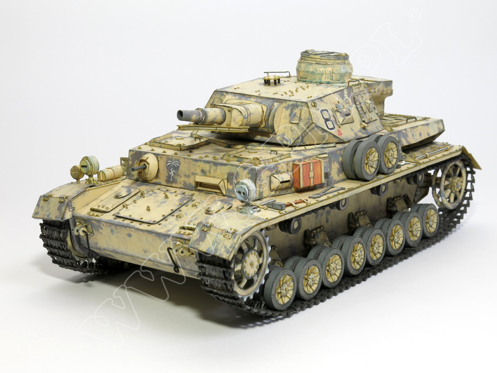


Code : WYP-wypgpm584
Manufacturer : WYPRZEDAŻ
54 PLN
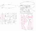
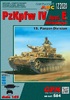
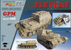
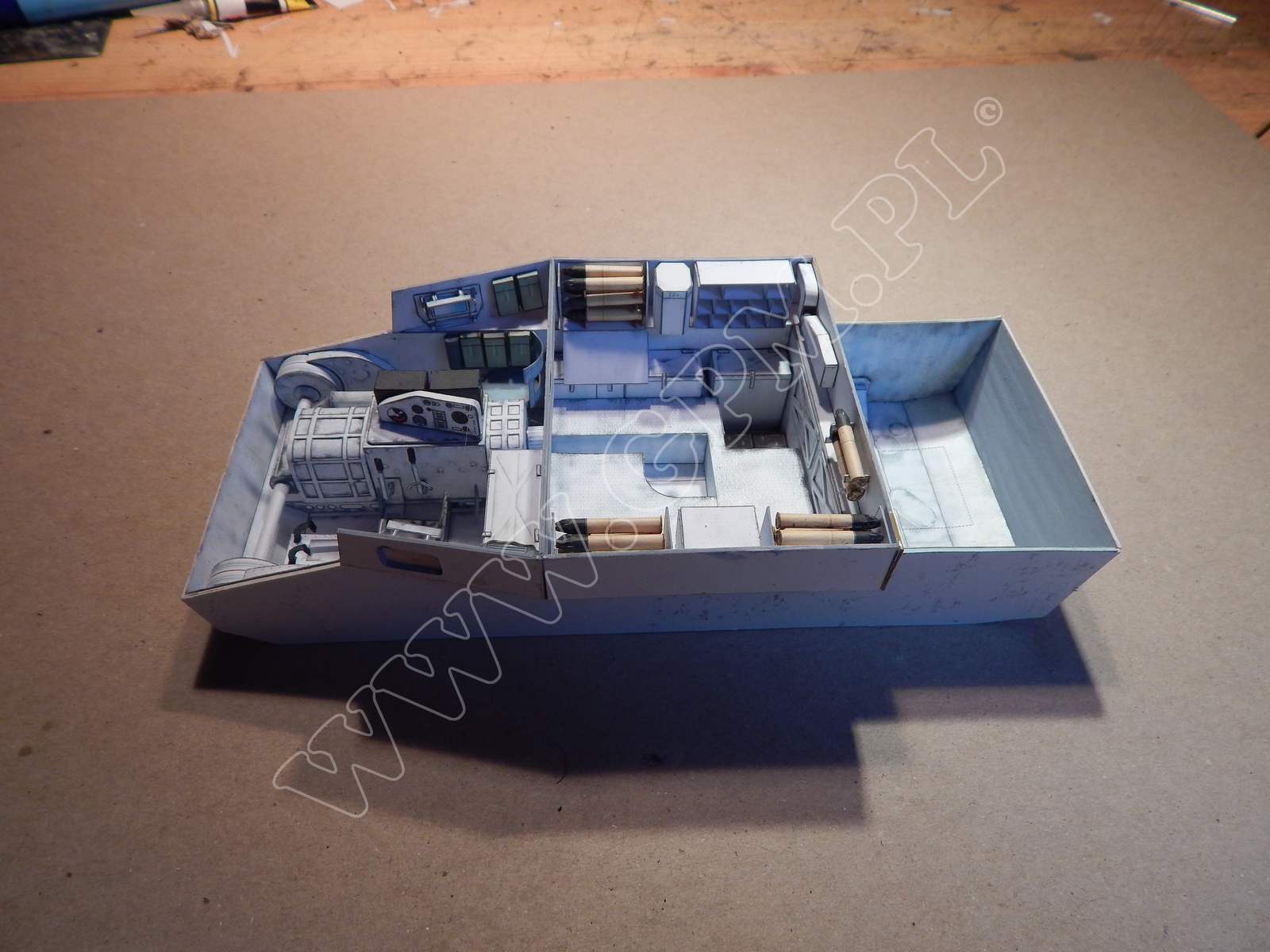
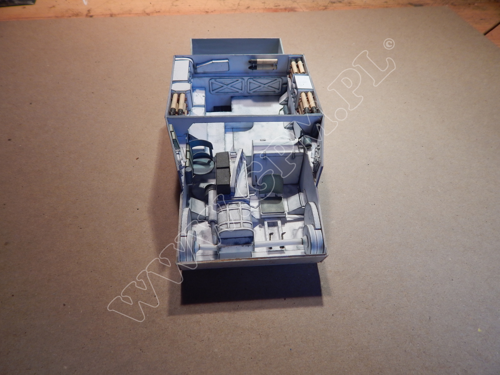
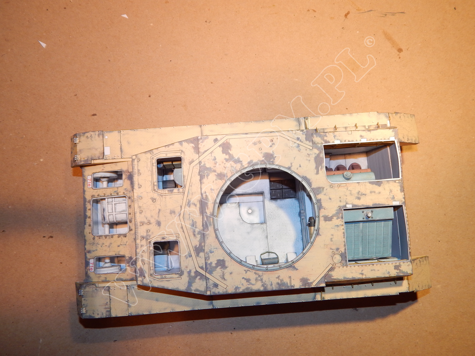
Reinforce parts 1, 1L, 1R with parts S1, S2, S3, S4, S5, S6, form a box out of them and glue the piece together. After attaching parts 2, 3R, 3L, complete the hull by adding remaining parts 1a - 1n, 3a, 3b, 4, 5, 6, 7, 7a, 7b, 7c. Inside the hull glue the floor 8, sides 8R, 8L, and frames 8a, 8b, 8c, 8d. Then attach the platform 9, 9a, and 9b. Parts 10, 10a, 10b glue as shown in the assembly drawing, and glue part 11 to frame 8. After making boxes from parts 12, 13, 14, glue them in the marked places. Attach part 15 to the floor as shown in the drawing. Now glue the accumulator 16 inside the compartment in part 9. Assemble parts 17, 18, 18a and glue them to frame 8a. Glue the hull sides 19, 19a, 19b to frames 8, 8d. From parts 20, 20a, 20b, 21, 22 make boxes and then glue them to parts 19aR, 19aL. Assemble parts 23, 23a, 23b, and attach them to part 8L. Glue part 24 to part 19aR, and part 25 to the hull side 8L.
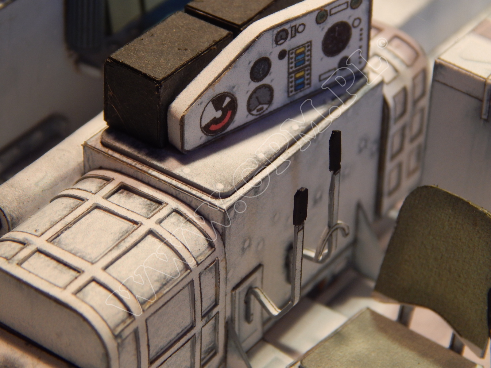
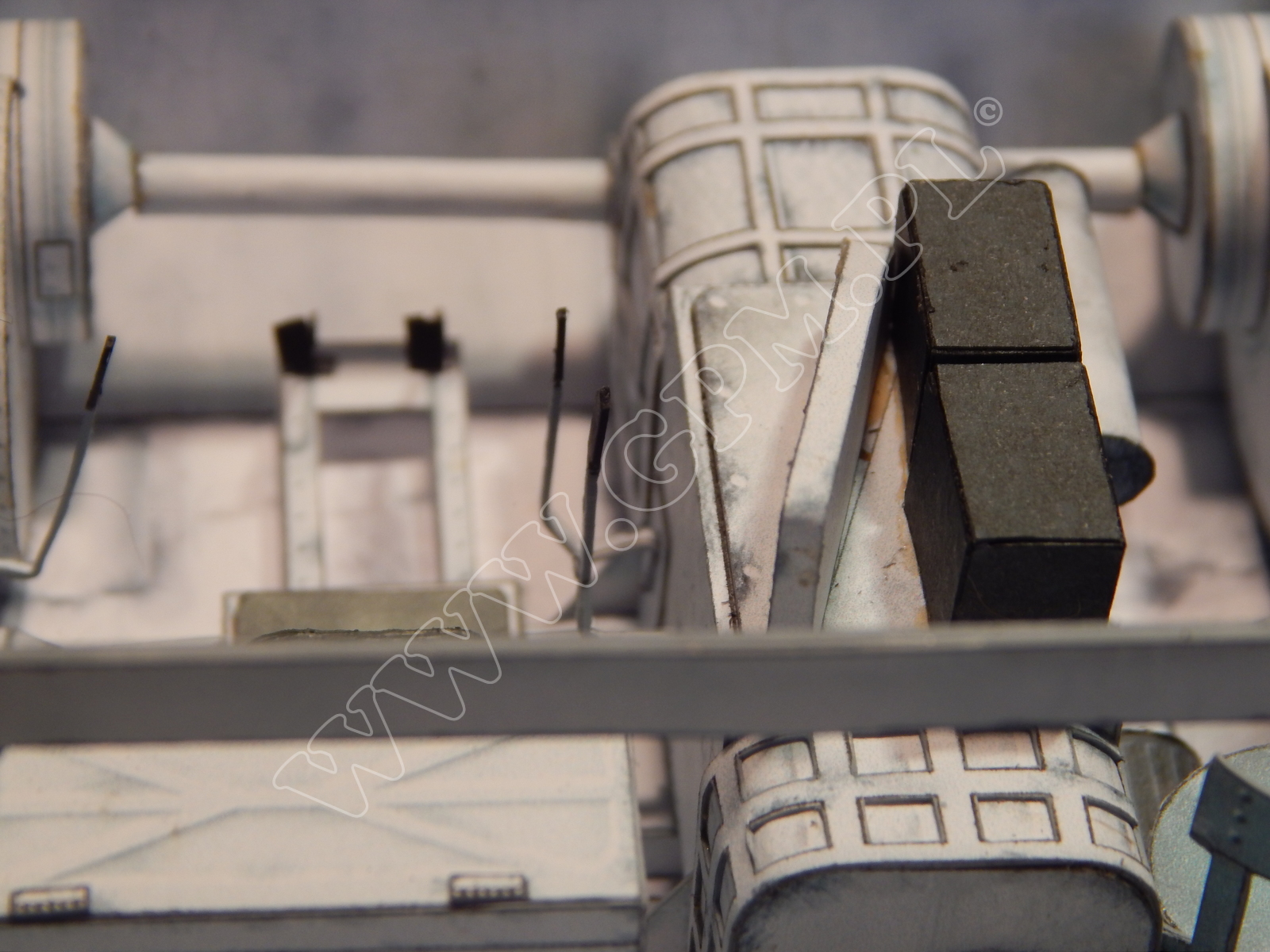
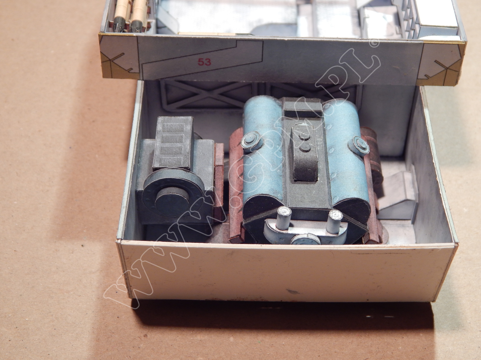
Referring to the drawing, assemble the gearbox from parts 26, 26a - 26m, and then glue the whole unit to part 15. Attach part 27 to part 26 as shown in the drawing.
Make clutches using parts 28, 28a, 29, 30, 30a, 30b, 30c, and attach them to the gearbox 26 and sides 8R, 8L. Glue part 31, 32 to part 26a.
From parts 33, 33a, 33b, 33c, 33d, 33e, 34, 34a, 34b, 34c assemble seats and glue them as shown in the drawing. Now glue throttle levers 35a, to parts 25, and 26. Glue parts 36 and 71 together and glue them to the hull.
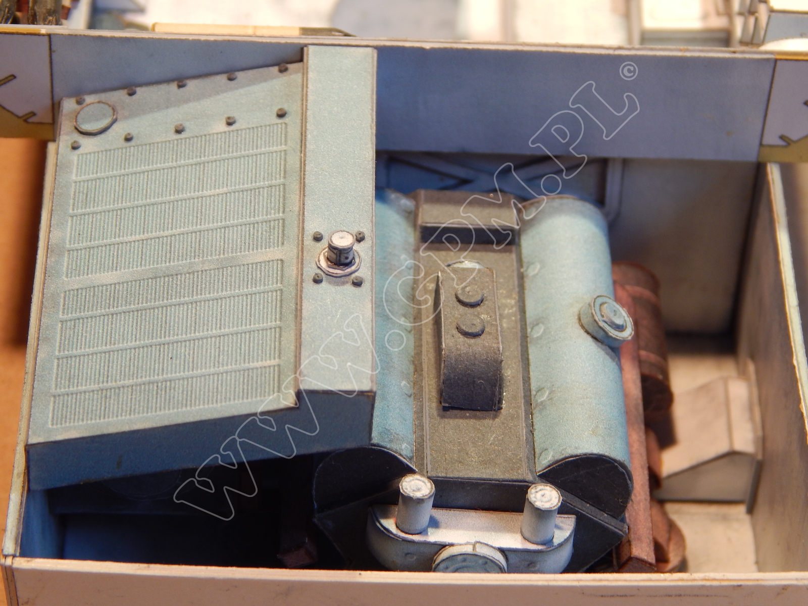
Make the engine body using parts 37, 37a - 37g, 38, 39, 39a, adding parts 40, 41, 42, 43, 44, 45, 46, 47, 48, 49 when the body is ready. Then glue the remaining parts 50, 51, as shown in the drawing.
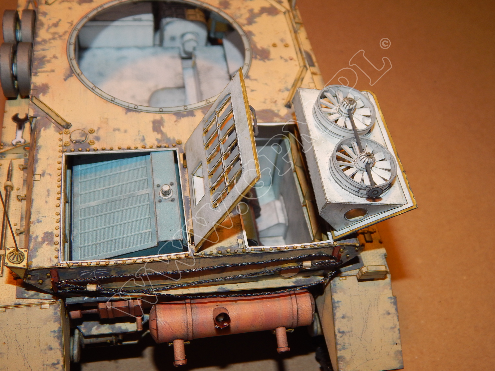
Now assemble ventilators from parts 52, 52a - 52m, 53. Parts 54, 54a, 54b make rounds that should be placed inside the boxes 20.
After gluing part 55 to frame 8a, put the rounds 54 on top of them. Complete the frontal hull armour 56 with parts 56a - 56m, and glue the whole unit to part 61. Place parts 57 as shown in the drawing.
Make shutters from parts 58, 58a, 58b, 58c, and glue them as shown in the drawing.
Reinforce part 59 with parts S7, S8 to obtain the rear hull side. When the piece is ready, glue it to the hull, and then insert parts 60, 60a to part 61.Complete the whole piece with parts 62, 63, 64 as shown in the drawing.
Glue hooks 65 in the marked places on the hull.
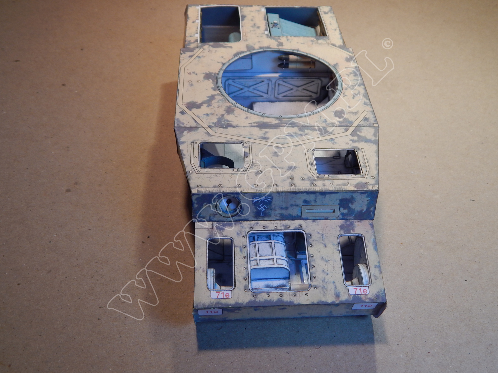
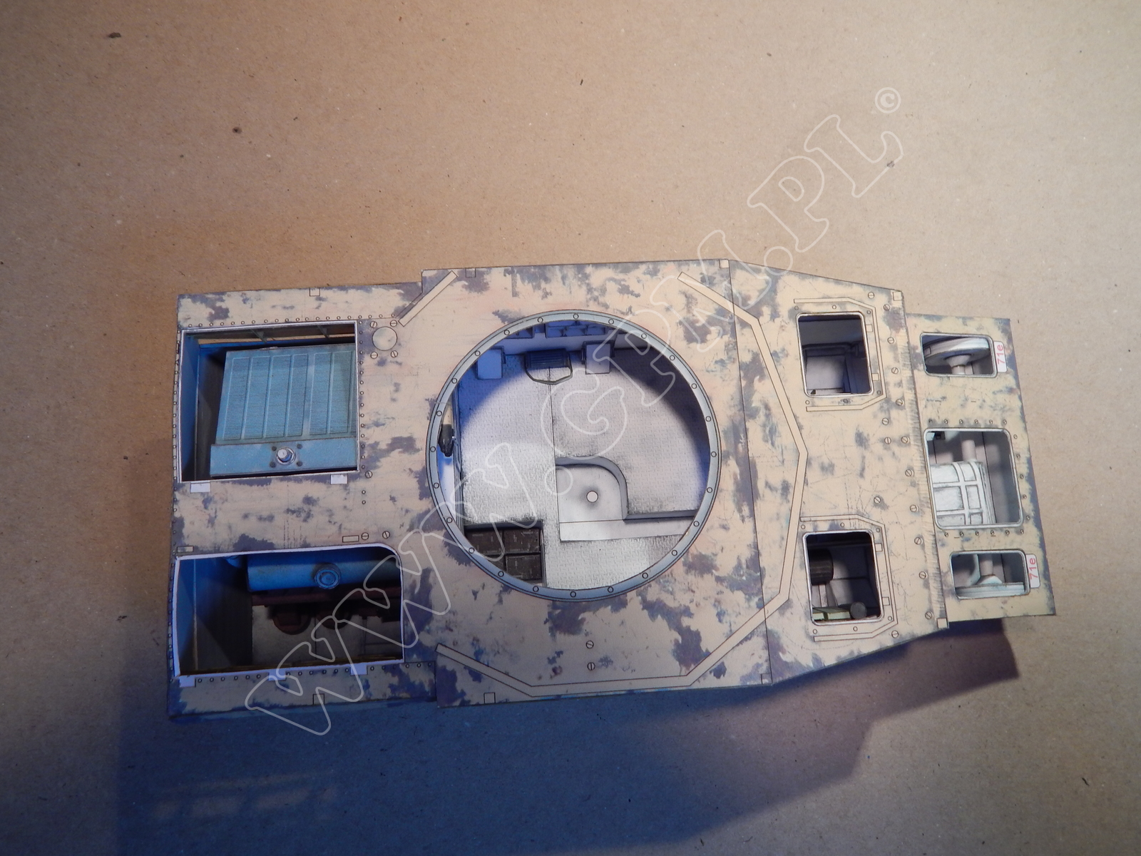
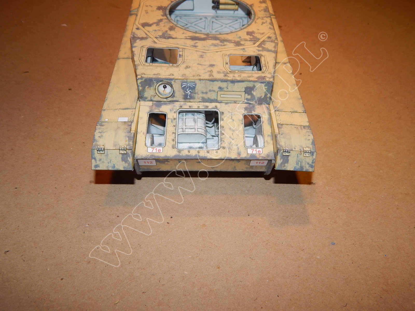
Next glue the visors 66, 66a to parts 61. Assemble parts 67, 67a, and 67b, as shown in the drawing and attach to part 61. Again, referring to the drawing, assemble parts 68, 69, 70. To part 71 glue previously assembled hatches - parts 71a, 71b, 71b1, 71c, 71d, and 71e. Glue part 72 to part 61. Make the rear hook from parts 73, 73a - 73f, and glue the whole unit to part 59.
Now make the track tensioner fastening from parts 74, 74a - 74c, 75, 76, 77, 78, and attach the whole piece to part 73.
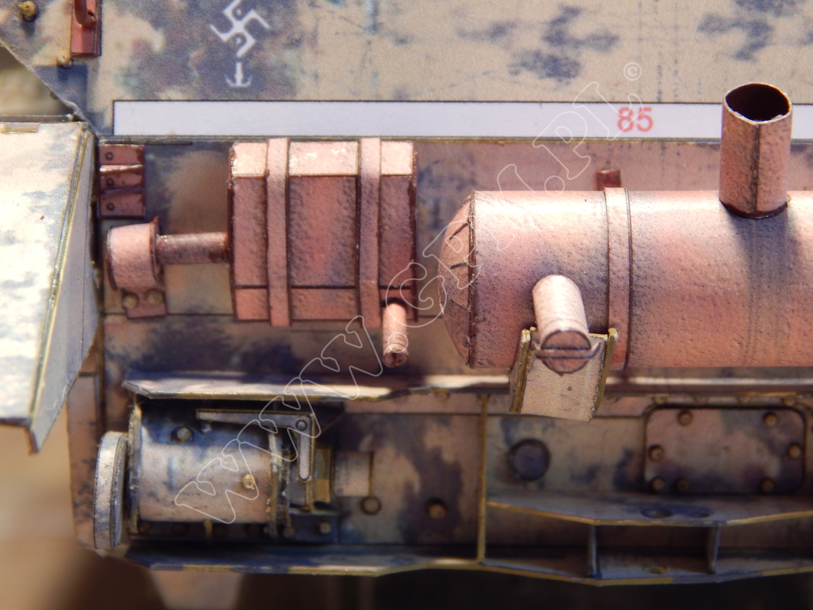
From parts 80, 81 assemble mufflers and glue them to part 79 and frame 59 as shown in the drawing. Glue parts 82, 83, 84, 85, 86 to part 59.
Now using part 87a, 87b, 87c, 87d, 87e, 87f, 87g, 87h assemble mud guards, and glue to the hull as shown in the drawing. Once more, referring to the drawing, place parts 88 on the mud guards. Glue reinforcing parts 89, 90 to the mud guards in the marked places. Place previously assembled parts 91, 92, 93, 94, 95, 96, 97, 98, 99, 100 on the mud guards according to the drawing, and then add parts 101, 102, and 103.
Assemble gas mask containers from parts 105, 105a - 105f, and glue them in corresponding places. Then assemble and glue part 106 as shown in the drawing, and finally make visors 107 and glue them to part 19.
MP40 machine guns are made from parts 108, 108a.
Refer to the drawing when making engine armour plates 109, 110, and hinges 111.Finally glue 111, 112, 113, 114, 115, 116 to the model.
Make the turret using part 117. Then insert all the internal equipment parts 117a, 117b, 117c, 117d, 117e, 117f, and close the whole piece with parts 117h, and 117g.
Assemble the gun mount from parts 118, 119, 120, 121. Add gun 122, and insert the piece as shown in the drawing.
After assembling the gun using parts 123, 124, 125, attach the shield 128, and then attach the whole unit to part 121.Glue parts 126 and 127 in the marked places. Make the turret mounting ring from part 129 and attach to part 117h. Assemble the box from parts 130, 130a - 130e, and using part 130f attach it to the turret.
Refer to the assembly drawing how to make the commander’s cupola from part 131. Now add parts 132 and 133.
Make the hatch from part 134 and glue it to the turret when ready. Glue part 135 to part 61.Use parts 136 and 136a to make the turret floor. Now add parts 136b, 136c, 136d, 136e, 136f, 136g, 136h, and glue the whole piece to turret 117g.
Now glue the visor 137 to part 121, assemble part 138, and glue it to the turret when ready, as shown in the drawing.
Attach two hooks 139 to the turret, and two to armour plates 61.
From parts 140, 140a, 140b make the turret shields, mounting them on hooks 141, 142 as shown in the drawing. Glue part 143 in the marked places on the mud guards.
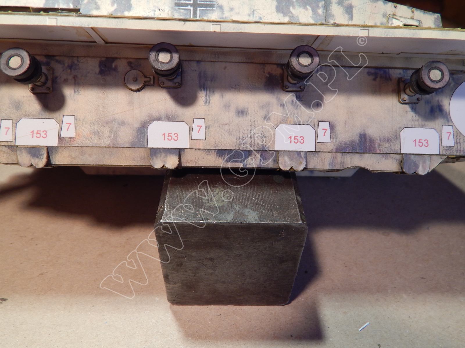
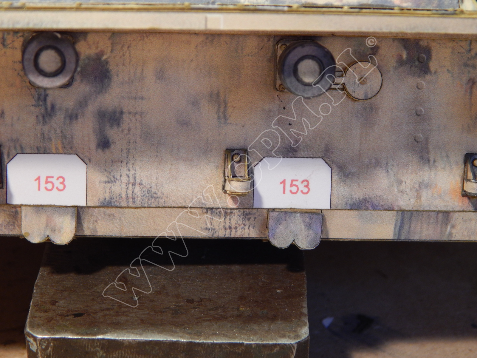
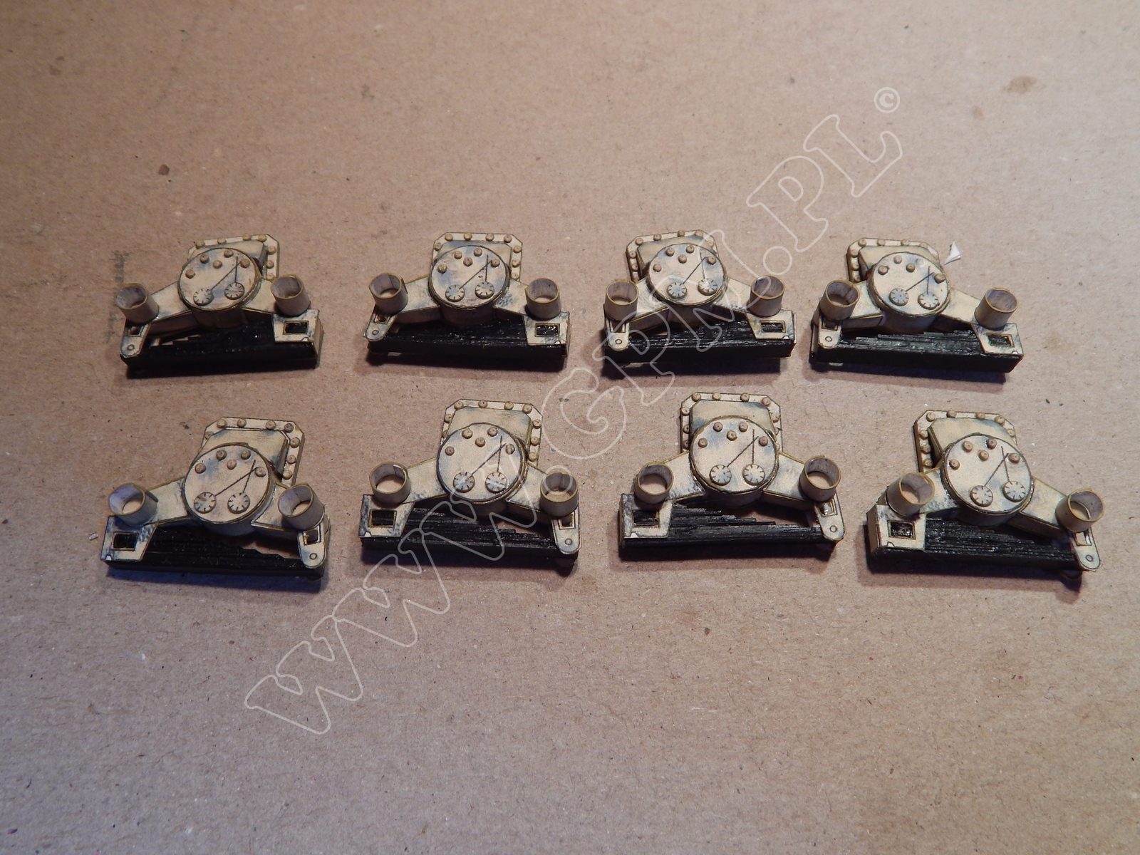
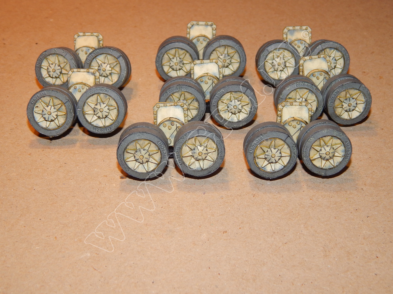
Parts 144 serve to make the hull armour plates, parts 146 make their fastening devices. Handles are made from parts 145, 146, and then glued to the hull according to the drawing. Now glue the rails 147, 148 to the handles. Glue parts 149, 150 together and then attach them to the model. From parts 151 make the machine gun and glue it to part 131m. Make helmets using parts 152. Now make the wheels mounts form parts 153, 153a - 153g and fasten to the hull sides. Use template X154 to make road wheels from parts 154. Fix the wheels to axles 154 when they are ready, and glue the whole units to the chassis 153b, 153c.
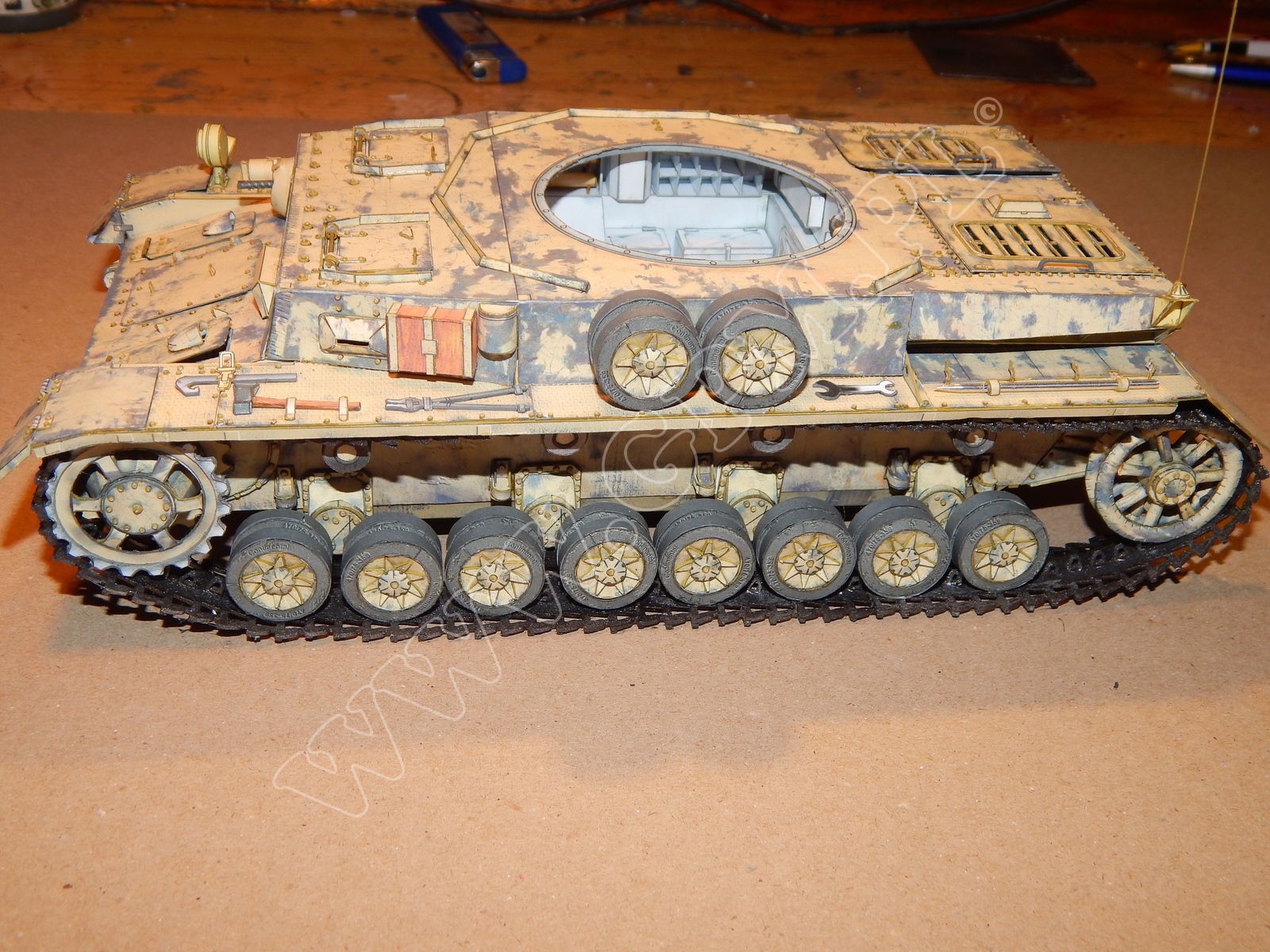
Refer to the assembly drawing of part 155 how to make the driving sprockets, and attach them to the hull. Assemble the track tensioners 156, and attach them to the trailing arm 78. From part 157 make support wheels and glue them to part 5.
The tracks can be made from parts G1, G2, G3, G4, G5, or from individual track plates G6, using also parts G5 and G7. Referring to the assembly drawings and the main diagram, localise and glue all the remaining parts.
Enjoy your work!
News